
Why a Spurious Emissions Preflight Belongs on the Ham Bench
An amateur radio spurious emissions test is not just something manufacturers do in a compliance lab. It is a practical station-maintenance habit for anyone using a handheld transceiver, homebrew transmitter, kit radio, transverter, external RF amplifier, or budget import radio. If a transmitter produces harmonics or other unwanted RF outside the intended signal, the operator can create interference well away from the frequency shown on the dial.
The issue is timely because enforcement attention has continued around out-of-band transmissions. ARRL reported an FCC warning involving out-of-band interference, a reminder that amateur operators are responsible for what their stations radiate, not merely what the front panel says. You do not need a million-dollar lab to catch many common problems before they become complaints, but you do need a careful setup, adequate attenuation, and a realistic understanding of measurement limits.
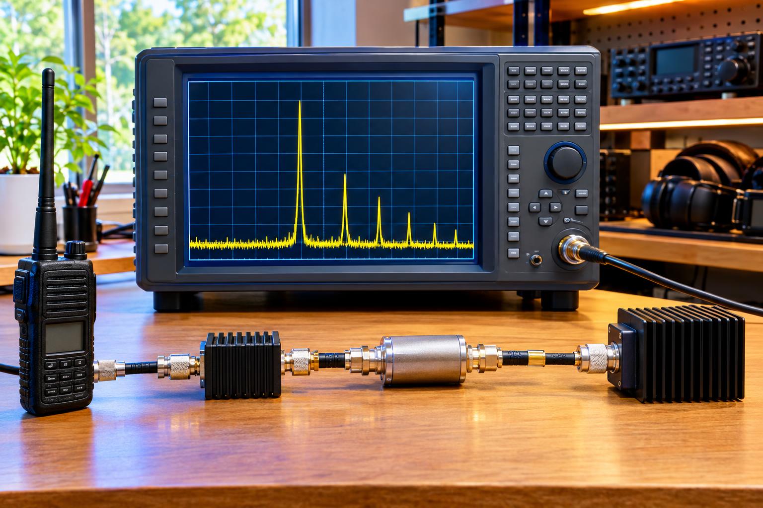
This article focuses on a safe, non-radiating bench workflow: dummy load, attenuators, spectrum analyzer or SDR, and a repeatable checklist. It is not a substitute for accredited compliance testing, but it can help you identify obvious harmonic, spur, overdrive, and filtering problems before connecting a transmitter to an antenna.
Spurious Emissions, Harmonics, and Splatter: Know the Difference
Spurious emissions are unwanted RF emissions outside the necessary bandwidth of the intended signal. In amateur work, the most familiar examples are harmonics: a transmitter on 7.200 MHz also producing energy near 14.400 MHz, 21.600 MHz, and so on. But not every unwanted signal is a simple harmonic.
- Harmonics: Whole-number multiples of the transmit frequency, such as 2x, 3x, or 4x the carrier frequency.
- Mixer products: Sum-and-difference signals created in transmitters, transverters, or poorly isolated stages.
- Oscillator leakage: Local oscillator or clock energy escaping into the output path.
- Broadband noise: Wide RF noise from poor biasing, oscillation, switching supplies, or overdriven stages.
- Splatter or key clicks: Excessive occupied bandwidth caused by overdriven audio, abrupt keying, ALC abuse, or poor waveform shaping.
A harmonic test is a good starting point because harmonics are easy to predict and often easy to see. But a proper preflight scan also looks above and below the fundamental for unexpected signals.
The Part 97 Starting Point
US amateurs should read the current text of 47 CFR §97.307, because the rule language is what matters. In plain terms, the rules require emissions outside the necessary bandwidth to be controlled and prohibit harmful interference from spurious emissions. The exact attenuation requirements depend on frequency range, power level, and equipment category.
As a practical bench reminder, many HF station transmitters and external RF power amplifiers are expected to have spurious emissions at least 43 dB below the mean power of the fundamental emission, with different provisions for some low-power transmitters. VHF and UHF requirements can be stricter or different, especially above 30 MHz. Do not rely on a memory shortcut when a close call matters; check the current rule text.
Also remember that regulatory compliance is not the only goal. A transmitter can technically pass a simple harmonic check and still cause RFI through overload, poor shielding, common-mode current, bad coax, loose connectors, or excessive occupied bandwidth.
Minimum Bench Setup
A basic preflight station can be assembled from common RF test tools. The key is protecting the measuring device while preserving enough signal to see weak unwanted emissions.
- Dummy load: Rated for the transmitter power, mode duty cycle, and test duration. Use a 50-ohm load with good VHF/UHF performance if testing higher bands.
- Fixed attenuators: Use enough attenuation to keep the analyzer or SDR input safely below its maximum rating. Choose attenuators rated for the power and frequency involved.
- Directional coupler or RF sampler: Useful for higher-power transmitters and amplifiers because it samples a small fraction of power while the main power goes to the load.
- Spectrum analyzer or SDR: A lab spectrum analyzer is ideal, but a good SDR can be useful if you understand its dynamic range and overload limits.
- Short, known-good coax jumpers: Bad coax and adapters can create misleading results or radiate RF inside the shack.
- Optional filters: High-pass, low-pass, band-pass, or notch filters can help reveal weak harmonics without overloading the receiver front end.
Never connect a transmitter directly to an SDR input. A 5-watt HT is about 37 dBm. If your SDR input is safe only around 0 dBm or below, direct connection can destroy it immediately. With 60 dB of attenuation, that 5-watt signal becomes about -23 dBm before cable and sampler losses, a much safer level. A 50-watt transmitter is about 47 dBm, so the same 60 dB chain produces about -13 dBm. Always calculate first, then add a safety margin.
A Step-by-Step Amateur Radio Spurious Emissions Test
1. Confirm the Test Path Before Transmitting
Connect the transmitter to the dummy load through the intended sampler or attenuator chain. Verify that the dummy load is attached, not the antenna. Check connector tightness, power ratings, and the maximum input rating of the spectrum analyzer or SDR.
If using an SDR, start with extra attenuation and low gain. SDR overload can create false signals that look like transmitter spurs. When in doubt, reduce gain and add attenuation; real transmitter emissions will track with transmitter power, while many overload artifacts change unpredictably with receiver gain.
2. Measure the Fundamental Safely
Transmit at low power first. Tune the analyzer or SDR to the fundamental frequency and confirm that the displayed signal is stable and not clipping the instrument. Note the displayed level and the total attenuation or coupling factor in the measurement path.
You do not always need absolute transmitter power to perform a relative dBc check. If the same measurement path is used, the difference between the fundamental and the harmonic is what matters. However, frequency response matters. Attenuators, couplers, cables, filters, and SDR front ends may not be flat from HF through UHF.
3. Scan Harmonic Frequencies
Calculate at least the second and third harmonics. For example, if testing at 14.250 MHz, check near 28.500 MHz and 42.750 MHz. If testing a 146.520 MHz handheld, the second harmonic is near 293.040 MHz and the third harmonic is near 439.560 MHz, which is especially important because it can land in another amateur band or near sensitive services depending on the transmit frequency.
At each harmonic, use a suitable span and resolution bandwidth. A narrower resolution bandwidth lowers the displayed noise floor but takes longer to sweep. Keep settings consistent when comparing levels, or record the settings carefully.
4. Apply Corrections
If you change attenuation between the fundamental and harmonic measurements, correct the reading. Example: the fundamental is measured at -20 dBm with 60 dB of attenuation. The second harmonic is measured at -72 dBm with 40 dB of attenuation. Because the harmonic measurement used 20 dB less attenuation, its comparable level would be -92 dBm relative to the original path. The difference is 72 dB, so the second harmonic is approximately -72 dBc, before accounting for frequency-response errors.
That example is simplified. A directional coupler may have different coupling loss at HF, VHF, and UHF. An SDR may show a sloped response. If the result is close to the legal limit, treat it as inconclusive unless you can verify the measurement chain.
5. Look for Non-Harmonic Spurs
After harmonic checks, scan a wider range around the operating frequency and across likely problem areas. Kit transmitters and modified radios may leak clock oscillators or synthesizer products. Amplifiers can oscillate outside the intended band. Switch-mode power supplies can add hash that rides on the transmitted signal.
A useful clue is repeatability. A real spur should appear when the transmitter is keyed into the dummy load and disappear when unkeyed. It should increase or decrease consistently with RF output power. If it stays present with the transmitter off, you may be seeing local RF, computer noise, or an SDR artifact.
Special Notes for HTs, Kits, and Amplifiers
Handheld Transceivers
HT testing is tricky because many handhelds use an antenna connector and chassis design that assumes a compact antenna, not a bench full of adapters. Use a proper adapter, keep the path short, and avoid stressing the connector. Test on low power first. Some low-cost radios have had public concern over harmonic performance, so checking the second and third harmonics is worthwhile before relying on one near repeaters, public-service events, or shared sites.
Homebrew and Kit Radios
For kits, test before final enclosure assembly and again after the radio is boxed. Shielding, grounding, output-filter layout, and connector bonding can change results. If a harmonic is high, inspect the low-pass filter values, solder joints, toroid winding count, relay routing, and ground return paths. A tiny construction error in an output filter can make a large difference.
External RF Amplifiers
Amplifiers should be tested at realistic drive levels into a dummy load. Overdriving an amplifier can create harmonics, intermodulation, and broadband garbage even if the exciter is clean. Verify band switching, output filtering, bias, and load match. A clean exciter does not guarantee a clean amplified signal.
Common Measurement Traps
- Instrument overload: The analyzer or SDR creates false harmonics because the fundamental is too strong.
- Radiating test leads: Poor shielding or loose adapters let RF leak into the receiver input by unintended paths.
- Wrong dummy load: Some loads are fine at HF but poor at UHF, where mismatch can distort results.
- Ignoring duty cycle: Digital modes, FM, and key-down tests can overheat loads and attenuators quickly.
- Assuming SDR accuracy: Many SDRs are excellent learning tools but need calibration and cautious gain settings for measurement work.
- Forgetting occupied bandwidth: A harmonic check does not prove that SSB audio, AFSK, FT8, FM deviation, or CW keying is clean.
What to Do If You Find a Problem
First, confirm that the signal is real. Add attenuation, reduce SDR gain, change cables, and repeat. If the spur tracks transmitter power and appears at the expected frequency, investigate the transmitter rather than trying to explain it away.
For high harmonics, inspect or add appropriate low-pass filtering. For VHF/UHF HT issues, the practical answer may be using a better-filtered radio or an external filter designed for the band and power. For amplifier problems, reduce drive, check tuning, verify band selection, and confirm that the load is actually 50 ohms at the operating frequency. For broadband noise, test with a different power supply and remove nearby digital devices from the setup.
If interference has already been reported, stop transmitting on the suspect setup until the cause is identified. The ARRL maintains general regulatory and RFI information that can help operators think through interference responsibilities and resolution steps.
Preflight Checklist
- Use a dummy load rated for the power, frequency, and duty cycle.
- Calculate transmitter power in dBm and choose enough attenuation before keying.
- Start at low power and verify the analyzer or SDR is not overloaded.
- Measure the fundamental and record settings.
- Check at least the second and third harmonics; check more if practical.
- Correct readings for changed attenuation, coupling loss, and known frequency response.
- Scan for non-harmonic spurs and broadband noise.
- Repeat after adding an amplifier, changing filters, or moving from bench wiring to the final enclosure.
- Do not connect the radio to an antenna until obvious problems are resolved.
Helpful References
For the legal baseline, read 47 CFR §97.307. For the enforcement context, see ARRL’s report, FCC Warns Licensee on Out-of-Band Transmissions. For practical interference background, ARRL’s Regulatory RFI Information page is also useful. ARRL’s technical article archive includes measurement and interference material, including a QST technical PDF on RF interference topics.
FAQs
Can an SDR replace a spectrum analyzer?
An SDR can be useful for screening, especially when paired with good attenuation and careful gain control. However, many SDRs have limited dynamic range, uncertain amplitude accuracy, and overload behavior that can mimic spurs. Treat close results as a reason for better measurement, not as a final compliance determination.
Should I test into an antenna?
No. Use a dummy load for preflight measurements. Testing into an antenna can radiate the very spurious emissions you are trying to evaluate and can expose the measurement to propagation, local signals, and pickup errors.
How low should harmonics be?
Check the current Part 97 requirement for your frequency and power level. As a practical station goal, leave margin below the applicable limit because hobby-grade measurement uncertainty can easily be several dB or more.
Does a low SWR mean the signal is clean?
No. SWR only describes how the load impedance relates to the transmitter system at the measured frequency. A transmitter can show a good SWR and still produce harmonics, spurs, splatter, or broadband noise.
Key Takeaways
- An amateur radio spurious emissions test is a practical bench habit for HTs, kits, amplifiers, and modified gear.
- Use a dummy load, adequate attenuation, and a measurement device that is protected from overload.
- Measure harmonics by comparing them with the fundamental in dBc, while accounting for changed attenuation and frequency response.
- Part 97 sets the regulatory baseline, but clean operation also requires attention to drive level, filtering, shielding, grounding, and occupied bandwidth.
- If a spur is real and repeatable, fix the station before connecting an antenna.