
Join our Exclusive Ham Radio Newsletter
A homemade RF probe is one of those small bench tools that can make radio troubleshooting feel less mysterious. With a diode, a capacitor, a resistor, a probe tip, and a meter connection, you can turn RF energy into a DC indication that an ordinary digital multimeter or oscilloscope can display. That does not make the tool magic, and it definitely does not make it a certified power meter. Used with realistic expectations, though, it can be extremely helpful.
The first thing to understand is that an RF probe is usually a detector, not a complete measuring system. The probe responds to RF voltage at the point where you connect it, rectifies some of that RF through a diode, stores charge on a capacitor, and lets your meter show a DC or slowly changing value. That reading may rise when RF is stronger and fall when RF is weaker, but it is not automatically the RMS voltage, peak voltage, peak-to-peak voltage, or transmitter power.
In a clean 50-ohm resistive system, the math connecting power and voltage is straightforward. Power equals RMS voltage squared divided by resistance, so 5 watts into 50 ohms corresponds to about 15.8 volts RMS. A sine wave at that level has a peak voltage of about 22.4 volts and a peak-to-peak voltage of about 44.8 volts. The catch is that a simple diode probe does not necessarily display any one of those numbers directly. Diode behavior, meter input resistance, capacitor value, frequency, layout, and calibration all matter.
That is why the best use of a simple RF probe is often comparative. Is there RF at this test point but not at the next one? Does the reading increase when the tuned circuit is adjusted correctly? Is the output lower after a filter, as expected? Did a transmitter stage lose gain after a component change? These are practical questions, and a probe can often answer them quickly.
A good starting application is transmitter testing into a dummy load. Use a low-power setting, a properly rated 50-ohm load, short coax, and a known external test point. If you also have a wattmeter or SWR bridge in line, you can compare the probe behavior with other station indications. The goal is not to certify power output with the probe alone. The goal is to confirm RF presence, compare relative levels, and build confidence in what your particular probe does under controlled conditions.
Calibration makes the tool much more useful, as long as you keep the word calibration in perspective. For a homemade probe, calibration usually means creating a local reference table for one probe, one meter, one general frequency range, and one physical setup. For example, you might feed a dummy load with 1 watt, 5 watts, and 10 watts at an HF frequency and record the DC reading from your RF probe at the same safe sampling point. The expected 50-ohm RMS voltages can be calculated, but the probe readings should be recorded empirically rather than assumed.
If you graph the results, you may notice that the response is not perfectly linear, especially at low signal levels. This is normal for simple diode detectors. A diode does not behave like an ideal switch that suddenly begins conducting at one exact voltage. Schottky diodes are popular for probes because they can respond better to lower levels than many ordinary silicon diodes, but they still have limitations. At weak levels, the reading can be more of an indication than a precise voltage measurement.
Loading is another major issue. A high-impedance RF probe is often described as though it barely affects the circuit under test, but high impedance does not mean invisible. The diode, capacitor, ground lead, wiring, and your body near the probe can all add capacitance or pickup. In a receiver front end, oscillator, filter, or tuned circuit, that small capacitance may detune the circuit or even stop an oscillator. If a circuit changes behavior when the probe touches it, the probe may be part of the fault you are observing.
The ground connection deserves special respect. A long ground clip can act like an inductor, an antenna, or an unwanted coupling path. It can also create a real electrical fault if you connect it where you should not. Chassis ground, circuit common, station ground, and protective earth are not always interchangeable in practical equipment. Never assume that clipping a probe ground lead to a convenient point is harmless, especially in unknown equipment, high-voltage circuits, tube gear, amplifier tank networks, or live antenna tuners.
Frequency also changes the story. A compact probe that behaves reasonably on HF may be erratic at VHF because physical geometry becomes part of the circuit. Lead lengths, enclosure shape, diode capacitance, the probe tip, the ground return, and the meter cable all influence the reading. If a probe gives repeatable results on 40 meters but strange readings on 2 meters, that does not necessarily mean the radio is strange. It may mean the probe is being used beyond its practical layout limits.
For receiver and kit-building work, use the probe conservatively. Receiver signals can be far too small for a diode probe to show reliably, especially near the antenna input. Better probe points include buffered oscillator outputs, documented test pads, coupling points, or stronger IF and mixer-related points where the circuit can tolerate the added loading. Always do the simple checks first: inspect the build, confirm supply voltage, verify DC bias, and make sure the expected signal source is present. An RF probe is not a substitute for a signal generator, oscilloscope, frequency counter, or spectrum analyzer when those are the right tools.
It is also important to know what the probe cannot tell you. It cannot prove harmonic purity. It cannot confirm modulation quality. It cannot establish regulatory RF exposure compliance. It cannot certify transmitter power for formal purposes. It cannot tell you the exact frequency of an oscillator. It may help you find where RF appears or disappears, but it should not be treated as a universal radio truth detector.
A practical RF probe becomes more valuable when it is labeled and documented. Record the diode type, capacitor value, resistor value, cable length, connector, meter used, and intended frequency range. Keep your calibration notes with the probe. If you change the meter, cable, or internal layout, assume the old table may no longer apply. The probe and the display instrument are a measurement system, not separate details.
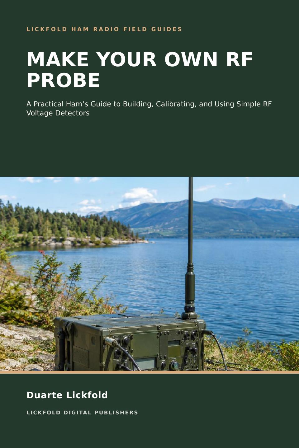
If you want to build this kind of tool carefully, Make Your Own RF Probe by Duarte Lickfold is a focused guide to choosing, building, calibrating, and using a simple RF voltage detector for amateur-radio work. It is especially useful if you want the practical benefits of a homemade probe while staying honest about safety, loading, calibration uncertainty, and the limits of simple diode detectors.
Explore the Book
Continue learning with Make Your Own RF Probe by Duarte Lickfold, published by Lickfold Digital Publishers.
Check our selection of Hamradio e-books
-

Worldwide DX under 5watts
$9.97 -

Portable Antennas That Pack Small
$9.97 -

Tame Your First HF Dipole
$9.97 -

Backyard Antennas for Tight Spaces
$9.97 -

First POTA Activation Playbook
$9.97 -
Copy CW Through Real Band Noise
$9.97 -
Reading the HF Sky
$9.97 -
FT8 Without the Frustration
$9.97 -
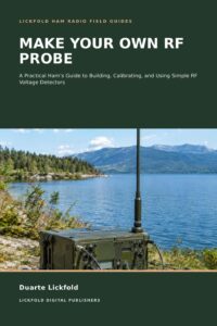
Make Your Own RF Probe
$9.97 -
Sale!

Mastering APRS
Original price was: $59.99.$47.99Current price is: $47.99.
A Comprehensive Guide – ebook
⭐⭐⭐⭐⭐ -
Sale!

Mastering FT8
Original price was: $59.99.$47.99Current price is: $47.99.
A Comprehensive Guide to the Ultimate Digital Mode – ebook
⭐⭐⭐⭐⭐ -
Sale!

Stealth CB Antennas
Original price was: $59.99.$47.99Current price is: $47.99.
A Masterclass in Innovation and Disguise – ebook
⭐⭐⭐⭐⭐ -
Sale!
Ace Your Ham Radio Exam
Original price was: $59.99.$47.99Current price is: $47.99.
Technician, General, and Extra Class – ebook
⭐⭐⭐⭐⭐ -
Sale!
DMR for Hams
Original price was: $59.99.$47.99Current price is: $47.99.
The Ultimate Beginner’s Guide – ebook
⭐⭐⭐⭐⭐ -
Sale!
D-STAR, DMR & Fusion
Original price was: $59.99.$47.99Current price is: $47.99.
A Beginner’s Guide – ebook
⭐⭐⭐⭐⭐ -
Mastering the 6-Meter Band
$47.99
The Ultimate Guide – ebook
⭐⭐⭐⭐⭐ -
Sale!
Integrating Ham Radio with Modern Technology
Original price was: $59.99.$47.99Current price is: $47.99.
IoT, Raspberry Pi, and More – ebook
⭐⭐⭐⭐⭐ -
Sale!
D-STAR, DMR & Fusion
Original price was: $59.99.$47.99Current price is: $47.99.
Guia para Principantes – ebook
⭐⭐⭐⭐⭐ -
Sale!
Ham Radio for Preppers
Original price was: $59.99.$47.99Current price is: $47.99.
The Essential Survival Communications Guide – ebook
⭐⭐⭐⭐⭐ -
Sale!

Mastering Marine Radio
Original price was: $59.99.$47.99Current price is: $47.99.
A Sailor’s Guide to Confident Communication – ebook
⭐⭐⭐⭐⭐

Enter shop